Showing posts with label Robosapien V2. Show all posts

Tuesday, April 9, 2013

Robosapien V2 - RIGHT Foot PCB Fix

Robosapien V2 - RIGHT Foot PCB Fix

March 05 2013

On the main control board, the leg connectors are along the bottom.

  • The RIGHT leg has seven connections
  • The LEFT leg has six connections


Here's the pinouts:


Robosapien V2 - Roached RIGHT FOOT (7-Wire) Main Board Connector

The connector to the main board on my Robosapien V2 was ROACHED.  Note the lower right corner of the white molded connector is totally bent from its normal shape.  Sigh.


This is not looking good.  Here's another pic:


After doing some very careful bending, I think I have it back in proper shape.  Hope so.

Rewiring the Robosapien V2 RIGHT Foot Board (7 Wires)

Here's a picture of the Robosapien V2 RIGHT (7-Wire) Foot Board:


Here's a pic with the wires nicely stretched out for easy identification:


Question.  Is it just me, or does this board seem a bit weird to you?  My meaning is this:  Just about every other wire entry on the Robosapien V2 robot is socketed.  


Even here we have some socketed wires:


  • The "AAA" battery connection is socketed (RED + BLACK)
  • The "tilt" sensor is socketed (GREEN)
BUT
  • The "bump" sensor on the FRONT of the foot is NOT socketed (ORANGE)
  • The "bump" sensor on the BACK of the foot is NOT socketed (BLUE)
What is going on here?  

Why is some stuff socketed, and others not?


It's a little weird.


Robosapien V2 - RIGHT (7-wire) Foot Board Block Diagram

Unable to find any documentation regarding the Robosapien V2 RIGHT (7-wire) foot PCB, I created this:


<check orientation of connector with pinout order>

Here's the "As Viewed" pinout for the Robosapien V2 RIGHT (7-wire) Foot Board, from LEFT to RIGHT:


  1. Blue or S-VCC
  2. Brown or lie
  3. Purple or GND
  4. Gray or F
  5. White or B
  6. Black or 
  7. Red or BAT -


Robosapien V2 - RIGHT (7-wire) Foot Board ABUSE

As you can see, the back of the 7-wire foot board has been totally roached by some ham-fisted hobbyist, or the person who assembled the unit in the first place.  

CRAP quality work:


What is that?  I would be embarrassed if that was the product of my labours.


Another view of the embarassingly bad quality Robosapien V2 RIGHT (7-wire) foot board:


Another view.  Trying to get the right angle with the camera / flash to capture just how awful this looks.

Time to get busy.


Using a soldering iron, I removed all of the old wires and as much of the old solder as I could, but after de-soldering, the story of the Robosapien V2 RIGHT (7-wire) foot board just got worse.  


The traces all DELAMINATED from the PCB.  This is because:


  • Whoever originally soldered the board used an iron that was too hot (very likely)
  • The RIGHT foot PCB, like the Right foot wire harness, was CRAP QUALITY (likely)
  • My little 40w iron was too hot (unlikely)
Here's a picture of the board with all the traces delaminating:


Another view:


Yet another view.  I'm a glutton for punishment:


I next used some de-soldering braid and my 40w iron to soak up the extra solder and get the board down to a nice, clean condition so I could refurbish it:

Here's what the Robosapien V2 RIGHT (7-wire) Foot Board looks like when its cleaned up:
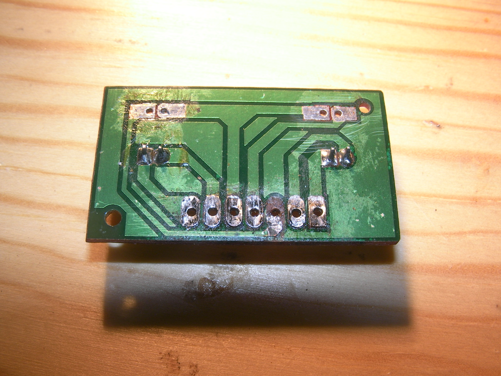


Another view:


A bunch more.  I was shocked:


Robosapien V2 - 7-Wire Female Dupont Connector Workaround

Unfortunately, the electronics store I go to does not have a 7-pin Female DuPont connector.

The best I can do is a 6 pin:


This is what you get when you only have 6-wire connectors available.  A 6-pin connector and a 2-pin connector with a "floating" pin.  Here's a couple of pics:


I then installed dual pin connectors where there were directly soldered wires for the local sensors.  Here's a couple of pics:


Here's the back of the unit after all of the soldering was done:


Here's the unit with the Robosapien V2 RIGHT FOOT FRONT BUMP SENSOR and the Robosapien V2 RIGHT FOOT REAR BUMP SENSOR installed.


What the Robosapien V2 RIGHT FOOT Board looks like when installed in the unit:


Robosapien V2 - Connecting the RIGHT foot (7-Wire) to the Main Board


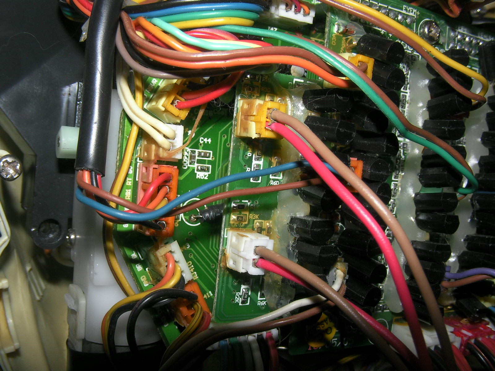
Here's a pic of the cable connecting to the RIGHT side of the Robosapien V2 Control Board.


A close up view of the Robosapien V2 RIGHT Foot Control Cable connected to the RIGHT side of the Robosapien V2 Control Board.


Here's a pic of the cable connecting to the Robosapien V2 RIGHT Foot Board.  Note the order of the wires.  Apparently, the connection to the foot board is 180 degrees from the main board.  Weird.  I wonder if Mark intentionally designed a half twist in there for some reason?

<insert pic of finalized male 2-wire 2.0mm DuPon connector inserted>


Everything now appears to be working OK

Fixed


Robosapien V2 - Foot Motors Rewire

Robosapien V2 - Foot Motors Rewire

While (clumsily) taking the Robosapien V2 apart for the first time, I somehow managed to shear off two wires from one of the connectors when the back plate, to which the arms of the Robosapien V2 are attached.  

In the V1 generation of the Robosapien, the skeletal structure is independent from the body panels.  You can take off all of the "coverings" and the machine below is 100% functional.  

Not so with the Robosapien V2, which is a shame.  If you want to get at the circuit boards of the Robosapien V2, you have to do without the arms.  I don't know who thought of that (or why), but I think it's a real shame.  Maybe it has something to do with the arms wiring harness leaving the body panels at the waist and entering the arms at the elbows?  

In any case, at the time I took it apart, I knew nothing about the way the robot was constructed and so was made quite anxious by this event of wires getting broken off when the robot fell into pieces on my workbench...eeek!

At that time, pretty much the only things I knew about those two broken wires was what I could see:

  • They connected to a connector that was yellow
  • They were brown and red
  • They (and the connector) came from the top left of the circuit board

I have since determined that this is the connector and wires for the LEFT FOOT MOTOR (robot orientation).  


Immediately below the yellow connector is a  white connector which I used as a reference in terms of what wire connected where, hoping that the two connectors were wired the same way.  The white connectors also had red and brown wires connecting to it and they led to the RIGHT FOOT MOTOR (robot orientation).


Seeing as this was early days, I forgot to take a picture of the damaged cables - so here's a picture of the repaired cables:


Why are the Robosapien V2 foot motor wires brown and red?  I do not know.

Interesting Observations:

  • The wires for the foot motors connect directly from the control board
  • The "foot board" PCB is not at all implicated
  • This is strange to me

Seeing as I know him personally, I asked the designer, Dr. Mark Tilden, to help me by explaining some aspects of the power arrangement in the Robosapien V2.  I was especially interested in the way the batteries were configured (3 x "D" cells + 2 x "AAA" cells). 

His kind response was that when he was developing the Robosapien V2 he elected to isolate the "noisy" 9v motor-oriented circuitry from the "neat" logic oriented circuity to keep things cleaner, signal-wise...and to get the Robosapien V2 to market quickly, which makes perfect commercial sense.  

He also commented that in later iterations of his own (and others) robots the power isolation/management had been simplified and so too was the battery strategy.


OK.  I understand now.


Robosapien V2 - Motor Board Variations?


I got a bunch of super useful information about the Robosapien V2 Motor Control Board from a couple of really targeted Robosapien websites, EVOSAPIEN and ROBOGUIDE:

I include the images below for both convenience and safety.  Both of the above websites are looking distinctly long in the tooth and EVOSAPIEN has not been updated for almost SEVEN YEARS:


(please, I want to capture this information just in case either site just winks out, which would be a real shame.  I'm just playing safe - please don't yell at me for snatching images...)


Classic Robosapien V2 Motor Board


Classic Robosapien V2 Motor Board Block Diagram


Classic Robosapien V2 Motor Board Pinouts


Classic Robosapien V2 Motor Board Header and Pad Pinouts

My Motor Board is not like your Motor Board

OK, the above is wonderful and I am really grateful to nocturnal for the resource.

But what if your Robosapien V2 Motor Board doesn't look like the one picured above?  

I ask this question because mine doesn't!  


Take a look for yourself:


Here's a block diagram of my Robosapien V2:


My "Exotic" Robosapien V2 Motor Board

Apparently, my RSV2 is either non-standard, or a different variation /generation:
  • My board is not rectangular.
  • My LEFT FOOT and RIGHT FOOT headers are in the mid left of the board.
  • My power entry headers are 2 x 4-pin horizontal, not 2 x 2-pin vertical
The pinouts for my board are basically the same, with these differences:

Left Foot


  • Brown
  • Red


Right Foot


  • Brown
  • Red


Power (White) - As Viewed


  • Black 
  • Black 
  • Red 
  • Red


Power (Red) - As Viewed


  • Black 
  • Black 
  • Red 
  • Red

Motor Orientation Tips:

I suggest that people take careful note of the motor orientation when re-wiring the Robosapien V2.  I used the "D" shape of the yellow core of the motor as a reference for wiring orientation because I noticed that the motor is actually flipped 180 degrees between the two feet.  

This means that on one foot the red wire is above, on the other foot the red wire is below:

For example, on this foot we have a red wire and a brown wire connecting to the motor with the brown wire connecting to the top of the motor and the bottom of the "D"-shaped plastic fixture.  In this case the "D" is backwards (or mirrored).


This foot is sane

On this foot we have two red wires connecting to the foot motor...

WTF?  


According to my strategy above, a brown wire should be connecting to the bottom of the motor and the bottom of the "D"-shaped plastic fixture, which in this case is right side up.


This foot is insane

So, I took a brown wire from my lovely bunch of 10-Core wires and placed it where it should go...


I then cut off the red bottom wire and took another photo with a white background in place because brown and red are actually pretty close to each other, colour-wise:


Replacement brown wire in place with white background to help with contrast and color identification.


<place photo of completed rewire here>


A Final Word on Robosapien V2 Motors

Here's an excerpt from an interview where Dr. Tilden talks about the motors inside the Robosapien V2:


"What kinds of motors are involved? "

"We build our own custom motors and gearboxes, pushing the concept of “toygrade” to the limits while still keeping costs low. In the RS2 we use 12 standard M130 motors for all actions, with a single M21 motor for the eye action. This type of modularity keeps costs low while encouraging high reliability. It’s always amazing how consistent a component gets when you order 27 million of them."

I looked up M130 and M21 motor types mentioned in the article and couldn't find anything except for Mercedes Benz engine types.  Huh?

Well, anyway, the foot motors are rewired.  

Fixed