Bringing a Prusa Mendel v1 Back from the Dead
April 02 2013:I got the green light today from Dr. William Liang, the Managing Director of DimSum Labs (the Hong Kong Hackerspace) to go ahead and try to resurrect his "dead" Prusa Mendel v1 RepRap printer. He's really bummed that the printer is no longer working and has high hopes that I can bring it back to life, and into service.

According to William, several well-meaning people tried their hands at "improving" the unit by altering various aspects of it once it had been finally assembled and commissioned into service.
Unfortunately, nobody finished anything they started and they never really got serious about documenting the impact of the changes they made to it (i.e. doing proper configuration management), so now nobody knows what was done. The machine is now a paradox and a mystery.
He was also kind enough to point out some Clearly Visible Problems, an assortment of Visible Upgrade Attempts and informed me of his suspicion that there were very likely a bunch of Invisible Upgrade Attempts made on the machine as well.
RepRap Ressurection, Part 1
Clearly Visible "Problems":
- A servo motor was tied by a nylon rope sliding in a silicone sheath to the "beam" of the unit, presumably to act as some kind of counter-weight to the lateral motion created when the printer moves from left to right (along its x-axis, I believe).
- A few tie wraps in places that (to me) made no sense. They weren't wrapping anything.
- The cooling fan on the firmware was not secured in place, which was worrying.
Visible Upgrade Attempts:
- Heated print bed (whatever that is - Dr. Liang had to show me that one)
- Silver cooling fan mounted to the extrusion nozzle (that one I could see for myself)
- Firmware changes?
- Other Hardware "tweaks"
Here's a picture of the RepRap with some of the above problems illustrated:

So, let's be honest here - I am really looking forward to this fix.
Like many of my most satisfying fixes, the challenge of this fix is multi-discipline and multi-dimensional, one part archaeology, one part technology, one part investigative journalism.
The very best aspect of this project? I don't know the first thing about this device.
I don't even know what it is called (they say it is a "RepRap"). I just thought it was a "3D Printer". I have no idea who designed it or why. Dr. Liang says he built it, but I don't know if he assembled it according to plans - there aren't any lying around - or did it in partnership with someone.
The bottom line is this is my kind of project. The patient used to be healthy and is now suffering. It is currently lying in pieces, broken, dusty and neglected. There is ZERO documentation and nobody wants to talk about it any more. A replacement unit is now in service so people couldn't care less if this thing ever powers up again (except, of course, for the guy who invested *his* time and money putting it into service in the first place - Dr. Liang). If I should bring it back to life I will be a *hero* to the guy who runs the lab and a *wizard* to those who choose to go there. To boot, it will become something I can *play* with once it's fixed and maybe even *improve* if I learn enough along the way.
HEY! I wouldn't have it any other way!
Like I said, this is my kind of project.
w00t!
Investigative Journalism:
I had a chance to talk to someone else in the lab that had that chance to observe one of the "friendly hands" who knocked this unit out of service. He said not to bother with it - that it was a complete waste of time. That I should find some other thing to work on. I call that "motivating talk".Here are my notes with respect to this machine, made as I examined it for the first time:

April 07 2013:
Danny said that he simply gave up in disgust after wrenching on the machine for an entire afternoon. He couldn't get it to do anything.
Hmmm, Danny is a smart guy....if he gives up on it...hmmm
Unfortunately for me, DannyH didn't really document any of the things he tried and wasn't that interested in talking all that deeply about it.
[ED: This is the same DannyH that purchased a new commercially produced 3D printer for the lab. People just love it!]
Observations
One obvious thing that is missing with this unit is a HOST COMPUTER. Apparently, the hard drive in the previous host computer *died* and went to heaven, taking with it all of the software used to drive the unit as well as the means to drive the unit. Hmm...
Taking a look around, I noticed that there were two laptops stored in a cabinet immediately below the area where the printer is located. Maybe they have something to do with the RepRap? Unfortunately, both are missing their hard drives. I asked around and found the people responsible for the disk-less laptops (DennisT - the owner?). DennisT works at night and can't come to the lab very often. He said the drives were "at home" and didn't really give me a firm commitment as to whether/if those hard drives would ever make it back to the lab. From the sounds of it, it looks to me like DennisT has donated the carcass of the machines but wants to keep his hands on the storage - - quite reasonable, when you consider the value of the data vs. the value of the (now obsolete) portable computer. Quite right.
Problem is, there's no drive for these laptops to boot an OS from, which leaves the RepRap dead in the water until another boot solution sufaces (TFTP boot? PXE boot? USB boot?).
This just made things a whole lot more complicated unless I can somehow secure a replacement, fully functioning laptop with OK hardware and a conventional boot environment.
Needing to kill some time, I took a physical inventory of all of the parts that were piled around the dead machine. There were various loose items as well as TWO cardboard boxes stuffed with "parts", some of which are pretty alarming for their very presence! I mean, why would you have FIVE loose servos in a box near a non-functional machine with FOUR servos on it?
All told, there were about 200 parts in the pile, everything from 2mm bearings to threaded rods to servos to optical sensors. A big grab bag.
April 09 2013:
Dr. Liang suggested I make use of an old ACER laptop that is running Windows hanging around the lab. OK! I'll take it! Where is it?

Here's our brave host computer, an ACER laptop. Looks fine to me.
I'll be integrating it into a formal RepRap Printing Area once I get everything up and running properly.
April 10 2013:
I've been doing a TON of online research on this unit (which I now know is a Prusa Mendel RepRap Printer invented by Dr. Adrian Bowyer, a Mechanical Engineer who invented the device while at the University of Bath.
Seeing as this is basically a little robot that is stationary in one sense and moves a *lot* in another sense, I looked at a TON of YouTube videos to try to orient.
Now I am a student of the RepRap Prusa Mendel. YouTube has been a great help, especially since there are several RepRap Mendel "series" of videos where people have recorded their experience constructing the device from the ground up.
The one that was (so far) most helpful to me is a series of about a dozen videos that chronicle the story of the genesis of a particularly orange RepRap Prusa Mendal printer:
Here's the YouTube Playlist
I really think that video is the best way to go with documenting something as complicated to assemble as the Prusa Mendel RepRap printer.
Text is nice. Photos are nice, but this thing is composed of a lot of parts has a fairly complicated assembly procedure and, once completed, moves in three dimensions!
Besides, I need a reason to brush up on my video editing!
April 16 2013:
I found two sets of handwritten notes at the lab today in the back of a drawer.
They concern some of the attempts to bring the RepRap Prusa Mendel back to life. Unfortunately, they don't say much, but here they are.
Note #1

Note #2

The one really valuable tidbit I did glean from the notes is that the RepRap controller board, which is called a RAMPS board (RepRap Arduino Mega Pololu Shield) is a RAMPS 1.2 board. This information is quite valuable in case I need to re-configure and "reflash" the Arduino MEGA card that is installed on this unit.
I also had a chance to take some photos of the unit:

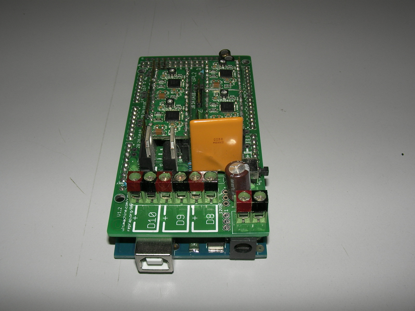
The Reprap Prusa Mendel ARDUINO MEGA and RAMPS 1.2 cards.
They are installed on the right rear side of the unit and are difficult to get to.

The Reprap Prusa Mendel "Hot End" cooling fan

The Reprap Prusa Mendel RIGHT Z-Axis Stepper Motor. Someone prefers tie wraps over screws. There are NO screws holding the stepper to the printed plastic assembly it lies on.

The Reprap Prusa Mendel LEFT Z-Axis Stepper Motor. While this one is not secured to the carriage by screws, at least the tie wraps are holding it in place, unlike with the RIGHT side.

The RIGHT lower clamp that holds the smooth rod in place. Over-tightened. Brittle. Broken.

Another pic of the broken clamp. The plastic used for this unit is *WAY* too brittle.
An Attempt to Connect
I "palpitated" the unit, moving all of the parts that are responsible for the X, Y Z axis and found out that the end stop switches were (mostly) out of alignment with the things they were supposed to be monitoring.From an assembly point of view, pretty much every bolt on the unit was loose - at best hand tight. Nobody had used any kind of product (loctite, nail polish, locking washers) to secure things in place, so the printer is very "loosey goosey" right now.
I downloaded and installed the windows version of the printrun software on the ACER. Then, like what I saw in the YouTube videos, I tried to use printrun to connect to the RepRap and test the stepper motors and monitor the heat bed and extruder temperature.
I tried to connect to the RepRap on COM3 / USB but I was unable to form a connection. Instead, the screen remained greyed-out and all I was in the dialog box was the following code:
M105
Then a bunch of special guests arrived on a special trip from China, so I ended up playing the host for the rest of the night.
April 17 2013:
Interesting news. Today I got an email response from Dr. Adrian Bowyer, the inventor of the RepRap family of 3D Printers. As it turns out he's a really nice guy. I had contacted him with some observations and questions about the RepRap (buildable-ness , feedstock sustainability strategy and also enclosing the RepRap with an IkeaHack).
His answers were thoughtful, well-measured and encouraging.
- He's up for anything that will help to drive the RepRap up the adoption curve and make it better.
- He does have some preferences as to which of my suggestions would be his priority (feedstock machine) but wasn't really pushy about it, which is nice.
- He thinks some of the other comments I made about the RepRap (particularly, that it is a little on the "flimsy" side and has a lot of lateral instability) may spring more from my own experience with this individual RepRap than would be representative of the entire class of this group.
- He would prefer not to enclose the RepRap to it can remain ultimately accessible to anyone who wants to see (and play with) the internals.
Doesn't look like he's a Bogart, which was something I kind of feared and which can happen sometimes when people work on something for a long time without a lot of social proof. So, I'm (guardedly) relieved that my first communication went well and I didn't get blown out of the water - which can happen sometimes when someone mis-perceives what is meant as a set of thoughtful, constructive questions as criticism.
I'm really looking forward to getting to know Dr. Bowyer - I like him already.
April 24 2013:
Removed the arduino from the RepRap today for some troubleshooting at home. Found out that the MEGA1280 that was connected to the printer was HOSED.
Good thing I'd already bought a MEGA2560
April 30 2013:
Finally got back onto the printer today. Took a big breath and started to dis-connect wires. -
- Big silver power supply - check!
- Black laptop power supply - check!
- tangle of white wires from heated bed - check!
- Assorted wires from servos - check
Disconnect RAMPS board for home testing - check!
Hmmm....will I ever be able to put this back together again?

Then a bunch of people arrived and I ended up playing host for the remainder of the night.
May 02 2013:
Got onto the RepRapRefurbRescue project again. Today I downloaded, customized and installed the RAMPS 1.2 firmware into the board. While I was at it, I corrected a bunch of stuff in the RepRap Wiki page concerning the 1.2 version of the board.
Time to make sure I understand all of the connectors:
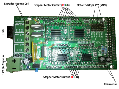
Hmmm, that power connection is *slightly* non-intuitive...

Fixed. Now only an *idiot* would connect the power wrong (that's me!)

Actually, why not do them all? The alternating black and red stripes are pretty...
Current for the Stepper Motors
I'm a little worried that someone has been playing with the current going to the stepper motors. Not enough current and they don't move. Too much current and you get magic smoke. :(I have no idea what they are set to right now. Here's a pic:

Turns out the stepper motors are driven by these little modules called STEPSTICK.
After a little research, here's some information about them:

OK, here's what I go in terms of adjusting the POTS on these little boards off of www.shapeoko.com
The A4988 stepper motor driver carrier is a breakout board for Allegro’s easy-to-use A4988 microstepping bipolar stepper motor driver and is a drop-in replacement for the A4983 stepper motor driver carrier. The driver features adjustable current limiting, overcurrent protection, and five different microstep resolutions. It operates from 8 – 35 V and can deliver up to 2 A per coil (MAX).
The potentiometers (POTS) on the drivers must be adjusted to control the current passing through the drivers. *See notes on heat below* We want to limit the driver to 1.0 amps without a heatsink and up to 1.5 amps with a heatsink, so we adjust the POT until we measure 0.4-0.6 volts at the marked point. Calculate this for yourself with the formula V(ref) = I(limit) * 0.4
Well, according to another post, the test point for this board is the pot itself...
There is a test point for VREF on the Pololu but it is missing on the Stepstick. Since it is just the wiper of the pot you can measure it there and it is easier as it is a bigger target. I hold the meter probe on the shaft of a metal screwdriver so I can see the value while I am turning the pot.
This particular tidbit I got off of http://forums.reprap.org/read.php?13,128220,188397

Re: Pololu Pot Tweaking?
by PLHS54 » Thu Jul 05, 2012 7:18 pm
This may seem like a dumb question, but when you are adjusting the drivers, should EVERYTHING be plugged in; all motors, power from power supply, and power from the computer to the arduino?
PLHS54
Posts: 60
Joined: Sun Apr 22, 2012 7:36 pm
Top
Re: Pololu Pot Tweaking?
by Burke LaShell » Thu Jul 05, 2012 8:41 pm
should EVERYTHING be plugged in
Here's some advice from the RepRapWiki:
If you think you may have mistakes you can install only one stepper driver during initial testing and risk only one stepper driver.
The trimpot on the stepper drivers controls the current limit. Turn it all the way down (counter clock wise) and back up 25%. Be careful to not force the trimpot, it is delicate. You will need to fine tune the current limit later.
Note that it is always giving the motors that much power, even when not moving, so if your stepper motor drivers are getting too hot, you may want to turn it down slightly.
OK, I'm just about ready to go, but I do need to double-check the volt/amp requirements of this board.
OK, I've got that now. 12v @ 5A minimum for the RAMPS board - who knows what the heated bed requires.
Here's a pretty wiring diagram I got off of the RepRap Wiki page for the RAMPS 1.2 board:

Got back to Dim Sum Labs tonight, but really to bring in the equipment that I want to drop off and also do my "soft launch" MakerMonday, where I made fridge magnets this week :)
I took a chance at the very end of the night to remove the heated bed from the RepRap:

Top side - aluminum plate layered with yellow clear-ish tape (KAPTON?) with a bunch of unmarked white wires leading into it...yaay :(
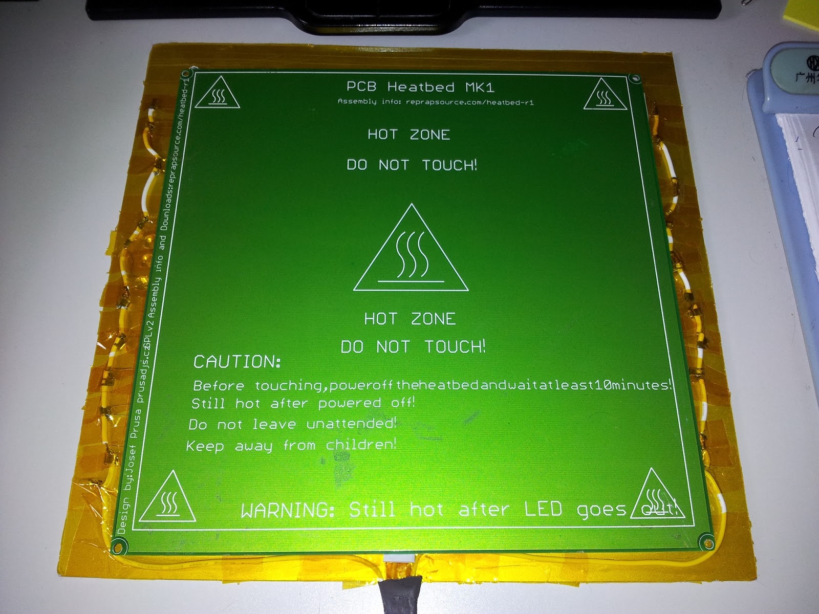

Here's a close up of the connector, bottom side. Hmmmm...I wonder if I can try to lift the PCB a little bit off the aluminum plate to see what's going on here...?

OK - the PCB wasn't connected to *anything*. It just lifted off...whaaaaat?

Underneath the PCB was a layer of what felt like slightly greasy, soft plastic sheeting. Honestly, I have NO idea what this stuff is...

Thankfully, the plastic stuff just lifts off of the aluminum plate. What I see here is probably a bunch of RESISTOR WIRE and a THERMISTOR

Here's a close up of the THERMISTOR - I have no idea of the operating characteristics of this device, so I think I'm going to leave this assembly alone if I can at all help it, and just re-build the PCB heated bed that wasn't attached to anything.
There's tutorials on the PCB heated bed that I can follow and not have to really worry about this aluminum thing until later :)
Once I get the PCB heated bed working, I might re-work the aluminum heated bed because I think that what the original designer was trying to do was to create a more UNIFORMLY heated print bed than maybe the PCB was going to deliver.
The Aluminum Thing:
Aluminum conducts heat quite nicely, and retains heat for a reaonable amount of time. I believe that the wires snaking around the bottom of the aluminum part are NICHROME wires (resistor wires) which get hot when current is passed through them. The greasy gray mat is a silicone mat, which has great heat resistance and the ability to disperse the heat from the resistor wires uniformly through the heat bed.
I found out a lot about this reading the following blog:
http://www.soliforum.com/topic/1022/homemade-nichrome-heat-mat/
Personally, if I was going to be designing a heat bed, I'd use a dual sandwich approach where a GRID of resistor wires (say on 1cm spacing) was implemented on a three or four layer bed with a large enough amount of thermal mass to maintain operating temperature with relative ease.
- Aluminum (w Kapton layer)
- Wool (600 degrees ignition temp)
- Resistor wire (north / south)
- Wool (600 degrees ignition temp)
- Resistor wire (east / west)
- Wool (600 degrees ignition temp)
The above may end up being a bit thicker, but it sure would heat nicely
May 07 2013:
I only had the chance to pick up a bunch of the parts that compose the Prusa Mendel at a VERY BUSY event that we had at Dim Sum Labs, so here's what I've got for today:

Here's the power supply. 12 volts, 20 Amps.
According to my research, this is plenty enough power to run the Prusa Mendel (12v @ ~6A) and the MK1 heated bed (12v @ ~10A) with about 20% spare "headroom" on the rating (which is wise). Rule of thumb on these ratings is back off about 25%, which in our case would mean that 15A should be the max load. Our total load is somewhere between 14A and 15A - close enough so even at full current draw (with everything cold) there should be enough volume of power available from this PSU to prevent anything from popping or catching fire.
BUT - A couple of fuses would be a good idea though, just in case a component goes crazy and attempts to draw infinite current. I will probably install separate fusing on the heated bed and the RAMPS, to just keep things safe.

Selector for input voltage.
We're on 220v so nothing to add here.
It's all good.

Here's the input and output rail.
Input on LEFT (Live, Neutral, Ground)
Output in MIDDLE (V-, V+)
Voltage adjustment pot on RIGHT (used to true up the voltage to 12v in case of drift)

Here's the top of the PSU.
Switching power supplies generate a lot of HEAT and RF NOISE.
So they usually have a Faraday Cage to reduce interference and passive (or active) head dispersion. Either a fan or a perforated cage is the norm.
BUT - don't spill anything on this unit!
I also got a new toy for Dim Sum Labs:
Infrared Thermometer:

This unit is rated to 200 degrees celcius, which should be OK for testing the various heated beds we've got on our hands (2 at the moment). It was inexpensive (HKD200.00 / USD25.64) and it's very nice looking.
Digital display and a laser guidance system.

Right side view...

Left side view...
The idea behind the purchase of this device is to see how much "thermal drift" these heat beds undergo AFTER they have reached operating temperature.
There's a couple of threads online about this problem and I'm interested in seeing if there's a way to resolve it in an elegant way that would contribute to the global RepRap community. Heated beds are a pretty critical element of consistent, high-quality output.
Stepper Motor:

I got my hands on a loose stepper motor to test the ARDUINO+RAMPS rig outside of the physical RepRap, which needs some TLC before I can power it up.
I will use this motor to help calibrate the current stepper motor pots on the stepstick module(s) on the RAMPS board.
"Old School" Heat Bed BOM:
(...derived from http://reprap.org/wiki/RepRapPro_Mendel_heatbed_assembly...)
What I Have
- MK1 Heat Bed
What I Need
- 1K Resistor (wattage? well, 1/4 watt is OK - just a resistor being driven)
- 10K Glass Bead Thermistor (WECL PART# 17-01-4103)
- Kapton Tape (heat resistant tape)
- 3mm LED
- 20ga Wire, one foot
Today I did a little more research regarding the MK1 heated bed and came across the following website, which I found most instructive:
http://josefprusa.cz/pcb-heatbed-final-mounting-and-wiring-solutio/
Here's what he has to say about the way he implemented the electronics on his heated bed:

OK, so now I know that the bed features TWO surface mount LEDs, mounted in opposite directions to each other in series with a 1K resistor. Good!
Here's my connections:

Pretty much the same, so its just a matter of putting the components in place...but there's a paradox at work here...
- If I put the surface mount stuff on LED side UP, the bed won't be flat any more.
- If I put the surface mount stuff on the bottom, the LED won't be visible...
Also, glass has a different expansion character than the PCB.
Here's an idea. How about implementing the glass with a clamping system of some kind?
I also think replacing the glass with a mirror is a good idea because the metal coating of the mirror will grab heat better, as well as looking prettier...here's a nice example....

So, the Heatbed Sandwich idea has now evolved to:
- Supporting layer (plastic or wood)
- Reflective Foil (Aluminum or Fire Blanket)
- Wool (non conductive insulator)
- PCB
- Mirror
This would all be mounted on four adjustable posts to help true up the tolerance between the heat bed and the print head to that of approximately a business card or two sheets of paper.
...tbc...
No comments:
Post a Comment