
I just love my Dualit 889 espresso machine.
I like the way it looks. I like the coffee it makes.
But, comparatively speaking, it needs a lot of TLC to stay in operations.
Over the years I've had to re-build it a couple of times.
- The bottom seal on the boiler baked away to nothing, causing a huge leak
- The mode selector rocker switch broke, forcing me to glue it.
- The power switch broke, forcing me to hard wire it
Now, some old problems have re-surfaced and some new ones have been accumulating, so today I decided to see what I could do about fixing them.
Now, some old problems have re-surfaced and some new ones have been accumulating, so today I decided to see what I could do about fixing them.
1) It has developed a leak (again!)
2) The selector rocker switch has broken (again!)
3) The power LED no longer turns on for some reason (this is new)
Suspicions:
The Leak:
I'm thinking that this is probably another seal gone bad.
The Broken Rocker Switch:
This has been a low-level, nagging issue for a really long time with this unit. It's broken before and I tried to use CRAZY GLUE to fix it. Didn't last long.
But, because it's only half-broken (and I'm lazy, and it's non-critical) it's been in this state for a long, long time. Like months. Actually, it's kind of useful in a weird way because it allows me to have a greater degree of control that when it is working "normally". That's probably a rationalization :)
The Failed Power LED Indicator:
The LED used to work (a nice RED color) whenever the machine was on.
Then it became a flickering LED, then it went out - never to return.
The HEATING light (YELLOW) is still working fine.
The LED used to work (a nice RED color) whenever the machine was on.
Then it became a flickering LED, then it went out - never to return.
The HEATING light (YELLOW) is still working fine.
The Rebuild:
Ok, let's get started with the rebuild...
The Dualit 889 requires a T10 and a T15 screwdriver set to be opened up.
Here you can see them lined up nicely in front of the machine.

The faceplate is held in place by four screws, one at each corner.
It's decorative and easy to remove.
I just took mine off and put it to the left.
You can just see it in the corner of this picture.
Please note that the nuts the screws turn into are loosely held in these special slots built into the case, so be careful to make sure you collect them too, not just the screws. If the nuts (they are square) fall out and roll under something they can be a pain to retrieve.

The next pair of screws to remove is about mid-way down the face, one on each side.

The next pair of screws to remove are a bit tougher to locate.
Flip open the back lid
Remove the water reservoir
The pair of securing screws will be revealed (and accessible)
They also need to be unscrewed.

Eight (8) screws later - Voila! The machine cracks open.
Two sets of wires connect the top of the machine to the body.
One set of wires is for POWER and PUMP wiring
One set of wires is for the POWER and HEATING indicator lights

Here's the INDICATORS wiring
My that looks wet!
No wonder the power light isn't working now.
Black, Red and Blue - hmmmm

Here's the "hot end" of the espresso machine.
(Hahaha! I've been working on RepRap printers for too long!)
There's a 3-way (mechanical) housing below that white clip-on assembly.
The tubes entering the 3-way housing are made of heat resistant material.
I think I remember that they are made of TEFLON.
A video of the action...

Steam is not supposed to emerge from within the machine...

This much steam is BAD for the internals of the machine.
Like the power indicator light...

Still, it makes a decent cup of coffee!
<slurp>....ahhh.....

Broken 3-way rocker switch.
This thing is really fragile. Third repair now.
This time I'm going to go ALL THE WAY with fixing it.

The POWER switch broke into two pieces about a year ago.
So I snipped off one of the blades from the back of the switch , so I just hardwired the unit to the on position by putting a common blade between the leads. While I have the machine open, I think I'll change out the transparent tape for some PVC tape. Safer and looks more pro...

Another view of the top of the machine...

One more...

Top view of the switch mounted to the white housing that clips to the 3-way.
How about we remove the screws around it and see what what we can see?

Screws out...

Alright, let's try to get this thing off the boiler without breaking anything...

3-way removed.
The big silver thing is the top of the boiler.
Hmm...the top of this boiler has TWO interesting characteristics:
- There's a discoloration that clearly indicates there is a leak here
- The exit point of the boiler (where the O-RING goes) is full of SCALE
Before I put this unit back together that scale needs to be removed.

Here's the bottom of the 3-way.
Note the RED silicone O-RING. One of those also fits into the top.
These things COOK over time, especially if they are in physical contact with the boiler.
The boiler gets HOT, as in over 100 degrees Celsius hot. Droplets dancing on it hot.

Getting rid of the scale by soaking the top of the boiler in vinegar (apple cider vinegar, don't have white!). Using Q-TIPS because that's what came to mind...

Soaking, soaking, soaking...

Maybe if I add more vinegar this will go faster?

Another view of the bottom of the 3-way switch

Doesn't hurt to coat everything made of rubber in this machine in silicone grease, which will lubricate, protect and (somewhat) restore old, tired rubber back to its originally springy self...

OK, Q-Tips are really not effective enough.
Let's try SOAKING a piece of paper towel in vinegar and jamming it into the hole...

While waiting for vinegar to do its thing, how about working on the rocker switch?
File stem of rocker switch with old, gnarly nail file.

File body of rocker switch with with gnarly nail file...

The exit point of the boiler.
Now nice and clean after some soaking and scraping with a sharp object....

There's a cotter pin holding the tube from the 3-Way to the group head.
An O-RING seals the connection.
While it feels loose to me, they don't leak. So...OK...

OK, everything coated with silicone grease and re-assembled, ready to go into service...

I even greased the travel of the switch.
Now it just *glides*...
Houston, we *still* have a problem...
Crap! What could be wrong?

Look again...

Wow! A CRACK!
Running almost the entire length of the unit!
I'll be darned!
At first I thought that this was just a seal issue, like what I had a long time ago with the bottom of the boiler. NOPE. Now, after fiddling with changing seals all afternoon, I see that the valve body (which is made of brittle, high temperature plastic) has cracked.
OK, Not surprising after 12 years of being in service, just a pain.

Time to get out the chemistry set.
First, soak valve body crack with acetone to soften it up. About a 5 minute soak
Next, soak 3mm ABS beads cut from a 3D printer filament in acetone for about 5 minutes...

Assembling the instruments for the surgical theatre....
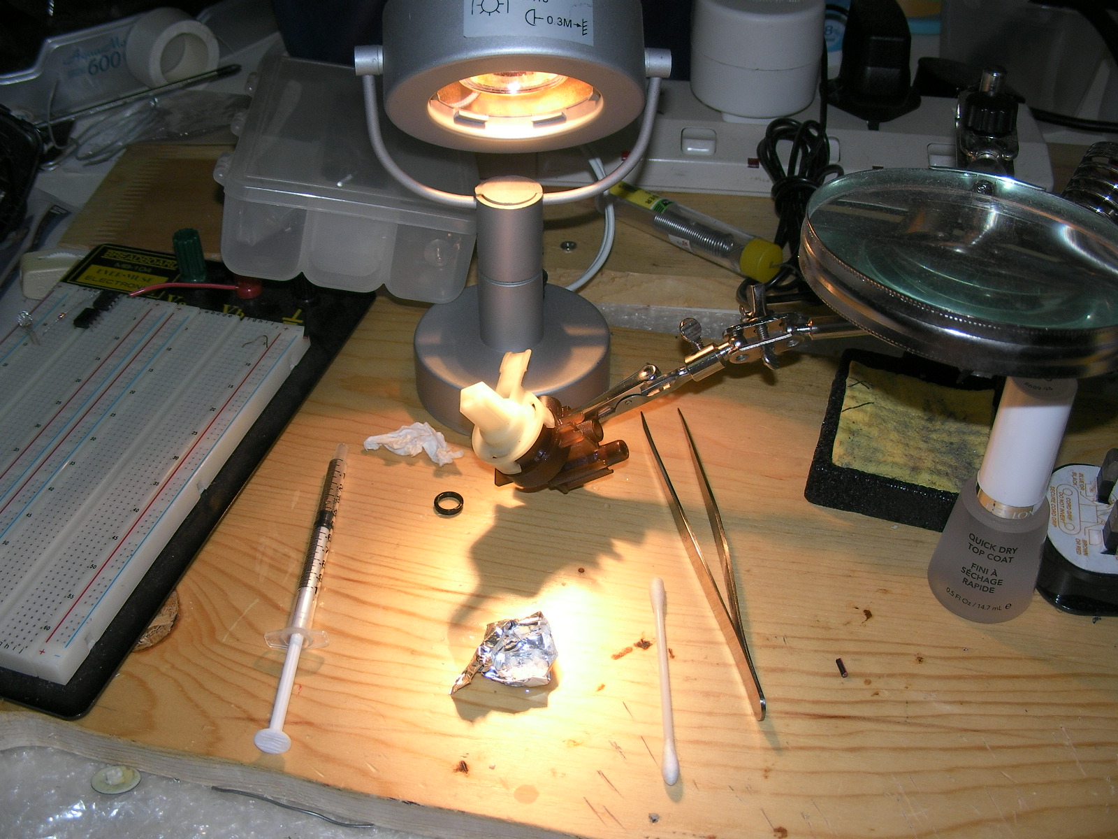
OK, the beads are *soft* now, time to start stuffing the assembly...

Stuffing, stuffing, stuffing...

More stuffing....

OK, now for the nail polish.
Gosh I hope its not too toxic....

More filament, this time a contiguous chunk to give the patch structural stability and hopefully some additional resistance to the 15BAR pressure this assembly experiences.
Cover with LOTS more nail polish...

Put second filament in place to give the first filament a buttress.
Load up with nail polish to give everything something to bind to...

Everything is bubbling and melting....good!...

Use a drop of nail polish to secure the central spindle of the 3-way rocker switch in place...

Set up working area for hot glue

Apply hot glue along perimeter of spindle.
Hope like crazy it adheres enough to matter...

Here's the cooled down unit. Blob-o-rama!

Here's a pic of the rocker switch Installed.
Boy I do hope I got the cogs registered right against each other...

Alright, everything seems to fit OK - even with all that extra glue loaded in there...

Another view of this crazy rocker switch...

The electronic INDICATOR panel is not OK.
Before, when powered on, it used to light up (RED).
Now, when the boiler is heating up it still lights up (YELLOW).
But one day the RED power light flickered and eventually went out
Now it does not light at all. It could have something to do with all that steam flying around...

The underside of the PCB.
I have no idea what the lighting scheme of this board is.
It looks like little rows of surface mount LED's
Hmmm...I just fiddled with these little light banks and now NEITHER light up. :(
You know, that might just be the right excuse to put a PID on this machine :)
But first, let's see if we can just get a couple of LED's to light up :)
The INDICATOR circuit in the Dualit is *very* reminiscent of a circuit described by William Liang at a recent HackJam ("Plugging LED's directly into a 220v Main without going POW!").
I wonder if I've just encountered Dr. Liang's circuit IN THE WILD.
Hahahaha! They all said he was crazy! This circuit is twelve years old already!
Well, maybe I'll just see what power is going through the unit and go from there...

Here's that clear tape situation all straightened away..

The bottom of the panel.
There's really nothing special here.
Except for the fact, of course, that neither light works now!

Decided to give myself just a bit more compressive power by adding an extra very thin washer under the original..

PLENTY of silione grease to help the rocker switch rock.
It's only 99% straight, so theres a (tiny) point of rocking resistance...

Well, if the panel isn't working, why not try to figure out what the leads mean and replace it?

Here's the leads labeled.
Pretty simple stuff really.
There's one neutral (black w/ red stripe).
There's a live coming off of the boiler thermal switch.
There's a live coming off the power switch.
So what's the voltage here? 220vac?
Let's check...
OK, the voltage is 220vac
I happen to have some extra power bar indicator lamps hanging around.
How about testing to see if they'll make a quick & dirty set of POWER and BOILER lights?
Alright, we have very encouraging results here!
Next step is to see if the BOILER light goes out when the unit reaches operating temperature.
I can't do that until the plastic weld has completely cured, which will take at least 6 hours.
Goodnight.
Bad News - The Plastic Weld:
The plastic weld was a total, complete failure. :(
When operating at temperature the entire assembly just gets yucky soft. Like marshmallow.
Now, the unit leaks worse than it did before! :(
BUT - I can still make coffee! :)
The only downside at the moment is that the machine is now spitting water everywhere. A *stream* of water is now issuing from the bottom of the machine and leaking all over the counter and the floor.
Time to call in the Europeans!
http://www.juraprofi.de
Time to call in the Americans!
http://www.shop.partsguru.com
Let' see what kind of answers we're going to get from them over the next couple of days.
Until then, I'm going to work on the POWER and BOILER indicator lights and put the machine back together (over a bucket!) with a piece of sponge stuffed in the crack to prevent the spitting.
<pic>
Good News - The Rocker Switch Refurb:
The good news is that the rocker switch is working just fine :)
tbc....
More of a note for reference: sold in the states/rebadged as Farberware Fino FPE100. And I'd have suggested using high temp epoxy or jb weld for the repair as it's external without trying to soften the assembly plastic and using filament which melts well below the temps produced by the boiler on these.
ReplyDeleteMay also note that these were made by Jura for Dualit
ReplyDelete